

Gear Flow Meter Technology
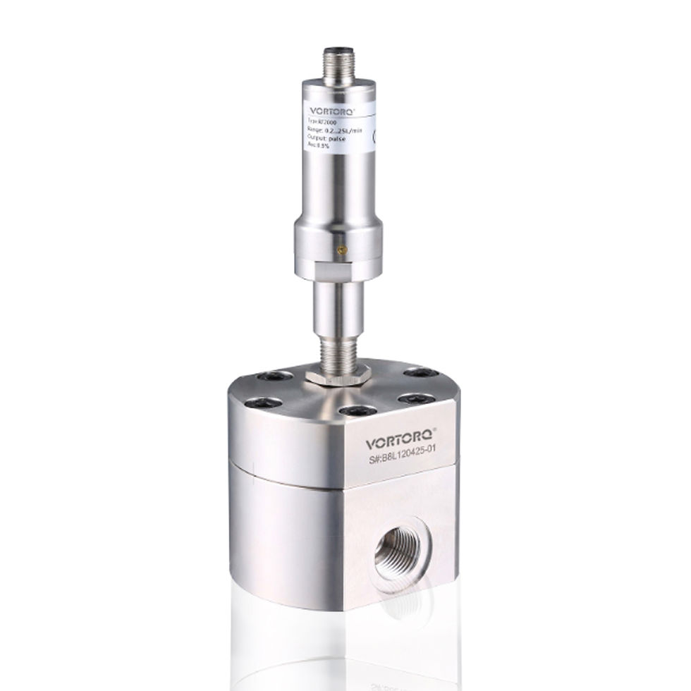
The VTFG200 Positive Displacement Flow Meter operates on the volumetric measurement principle, using rotating gear wheels that move in proportion to the flow rate. A sensor detects the movement of these gears through the meter's housing wall.
This flow meter is unaffected by fluid viscosity and offers a high turndown ratio, exceptional accuracy, high resolution, and quick response—making it ideal even for measuring extremely low flow rates.
The VTFG200 is bi-directional and can also be used to determine cylinder positions without causing wear or damage to internal components.
When equipped with journal bearings, the VTFG200 is capable of accurately measuring low- or non-lubricating fluids, including paints, adhesives, resins, and sealants.
The VTFG200 series offers eight measuring ranges, from 0.006 to 1 L/min up to 4.0 to 450 L/min, with optional output configurations including pulse, current analog, and voltage analog signals.


Key Features
-
High-pressure rating
-
Suitable for a wide range of viscous media
-
Excellent repeatability and accuracy
-
Selectable pulse or analog output
-
Wide measuring range
Description
As fluid flows through the VTFT200, it causes the rotor to rotate. Each time a rotor blade passes the sensor, it generates an electrical pulse. The frequency of these pulses is directly proportional to the flow rate. By combining the rotor’s revolutions per minute with the meter's K-factor (number of pulses per gallon), the flow volume passing through the unit can be accurately determined.
The VTFT200 series is ideal for measuring fluids with medium to low viscosity, such as water, light fuels, solvents, hydraulic oils, and lubricating oils.


Key Features
-
High pressure resistance
-
Fast response time
-
High repeatability and accuracy
-
Range specific width is up to 50:1
-
Compact structure
Description
The VTFT400 features a magnetic detector and a magnetic rotor (impeller). When fluid flows through the pipe, it drives the rotor to spin. The rotor speed is directly proportional to the fluid’s velocity. The magnetic detector senses the rotor speed and converts it into a standard industrial electrical signal or visual display.
The VTFT400 is suitable for measuring fluids with medium to low viscosity, such as light fuel oil, hydraulic oil, and lubricating oil. An optional viscosity compensation function allows accurate measurement even when fluid viscosity changes with temperature.
With up to 12 impeller blades, the VTFT400 offers a faster response time and higher resolution compared to other models in the series.

Key Features
-
High pressure rating
-
High and low temperature resistance
-
Low pressure loss
-
Fast response time
-
High repeatability and accuracy
Small structure
Description
The VTFT500 Series flow meters feature magnetic detectors and a magnetic turbine. As fluid flows through the pipe, it drives the turbine to rotate. The turbine’s speed is directly proportional to the velocity of the fluid. The magnetic detector measures the turbine speed and converts it into a standard industrial electrical signal or display output.
The VTFT500 Series is ideal for measuring fluids with medium to low viscosity, such as water, light fuels, solvents, hydraulic oils, and lubricating oils. Optional viscosity compensation enables accurate measurement even when fluid viscosity varies with temperature.
These flow meters offer a wide turndown ratio of up to 100:1, and the ultra-high-precision models deliver accuracy of up to ±0.1%.

Key Features
-
No moving parts – low maintenance and no pressure loss due to obstruction-free design
-
Wide measuring range: DN10 to DN500
-
Suitable for a variety of media, including acids, alkalis, salts, sludge, pulp, and other conductive fluids
-
Digital LCD displays both instantaneous and total flow
-
Wide operating temperature range: -20°C to 180°C
-
High reliability – direct PLC-compatible output
-
Fully digital signal processing with strong anti-interference capability and high measurement
Description
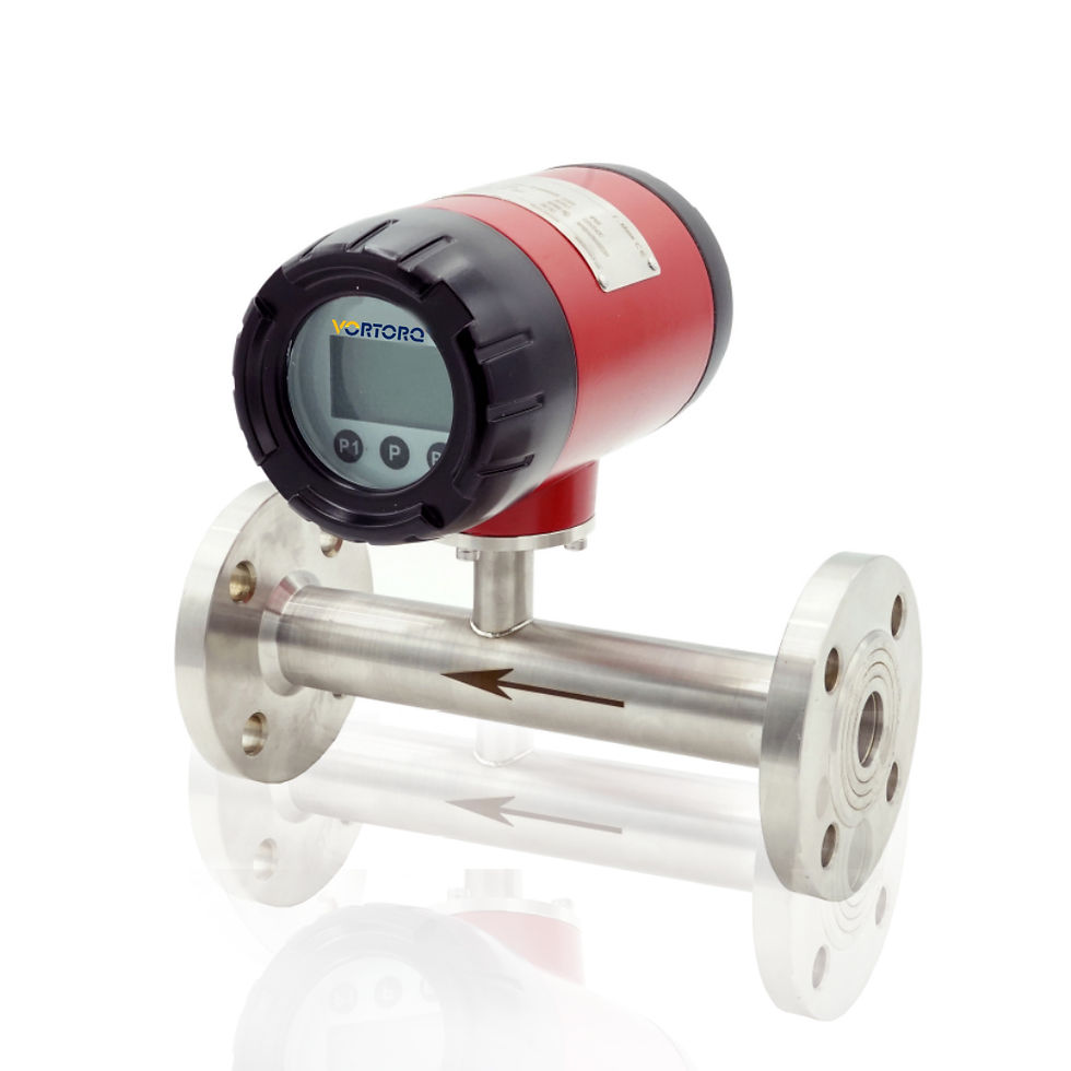
The VTFM100 Electromagnetic Flow Meter operates based on Faraday’s Law of Electromagnetic Induction. When a conductive liquid passes through a magnetic field perpendicular to the direction of flow, it generates an electric potential proportional to the average flow velocity.
This induced voltage is detected and transmitted to the signal converter, where intelligent processing calculates both instantaneous and cumulative flow values. The flow data can then be displayed locally and communicated to control systems for monitoring and automation purposes.

Key Features
-
Compact design saves installation space
-
Corrosion-resistant sensor technology
-
All-electronic design with no moving parts
-
Automatic viscosity and temperature compensation
-
Optional pulse or analog output
-
Low pressure loss
-
Contamination-resistant
Operating Principle
Based on Faraday’s law of electromagnetic induction: when a conductor moves perpendicularly through a magnetic field (B), a voltage (U) is induced.
In the case of the electromagnetic flowmeter, the conductor is a flowing conductive fluid. The magnetic field is oriented perpendicular to the direction of flow. Electrodes (E1 and E2) positioned in the flow path detect the induced voltage (U), which is directly proportional to the flow velocity (V) of the medium.
Formula:
U = K × B × V × D
U = Induced voltage
K = Meter constant
B = Magnetic field strength
V = Flow velocity
D = Distance between internal electrodes
The induced voltage (U) is then processed and converted into a standard electrical signal for display or output.

Key Features
-
Wide measurement range
-
Programmable setpoint and measurement range via onboard keys
-
Advanced parameter settings available through handheld device or PC
-
8 LED indicators show switching status and flow trend
-
Compact design (36 mm diameter)
-
Selectable output options: PNP / NPN / Relay
-
IP67 protection rating for robust operation
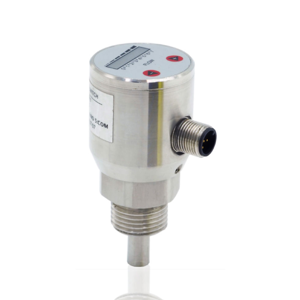
Operating Principle
The VTFC 08 operates on the thermodynamic principle. It contains two temperature sensors within the probe:
-
One measures the medium's actual temperature.
-
The other is heated slightly above the medium temperature.
-
When the medium flows, it carries heat away from the heated sensor. The temperature difference between the two sensors varies depending on the flow rate. This difference is used to calculate and monitor the flow.
Additional Features:
-
Durable all-metal housing
-
LED display for real-time flow and switching status
-
No moving parts, reducing maintenance needs
-
Suitable for various types of media

Key Features
-
4-digit LEDs
-
Flow velocity/percentage display
-
Wide measuring range
-
Measuring span programmable
-
PNP/NPN programmable
-
4..20mA/0..20mA/1...5V/0...5V output
-
programmable
-
Rotatable indicator,easy to read,robust display
Operating Principle
The VTFN3000 is based on the thermodynamic principle and contains two temperature sensors inside the probe:
-
One measures the actual temperature of the medium.
-
The other is slightly heated above the medium’s temperature.
-
As the medium flows, it dissipates heat from the heated sensor. The difference in temperature between the two sensors changes in proportion to the flow rate, allowing accurate measurement.